The Complete Guide To O-Ring Seals: Design Theory, Material Selection, Gland Engineering, And Failure Analysis For Maximum Reliability
Release time:2026-08-17
Visits:255
The O-ring seal represents perhaps the most elegant and cost-effective sealing solution ever devised by engineers. This simple toroidal ring, with a circular cross-section, has been quietly enabling technological progress since its patenting in the late 19th century. Today, O-rings are found everywhere—inside the fuel injectors of your automobile, within the hydraulic actuators that control aircraft flight surfaces, in the pharmaceutical pumps that dispense life-saving medications, and even in the space suits that protect astronauts during extravehicular activity. Despite their ubiquity and apparent simplicity, the engineering principles that govern O-ring performance are surprisingly sophisticated, and failures resulting from improper specification or installation can have consequences ranging from inconvenient to catastrophic.
The Fundamental Sealing Mechanism
Understanding how an O-ring works requires appreciating the concept of contact stress. When an O-ring is installed in its gland and the mating surface is brought into position, the ring undergoes an initial squeeze, typically 10-25% of its cross-sectional diameter for static applications. This squeeze generates a contact pressure at the sealing interface that exceeds the pressure of the fluid being sealed. As system pressure is applied, the O-ring is forced against the low-pressure side of the gland, and the elastomer behaves somewhat like a highly viscous fluid, transmitting the pressure hydrostatically and increasing the contact stress at the sealing surfaces proportionally. This self-energizing behavior means that a properly designed O-ring seal actually becomes tighter as system pressure increases.
This fundamental mechanism has profound design implications. If the initial squeeze is insufficient—perhaps due to an oversized gland, an undersized O-ring, or excessive surface roughness—the seal may leak at low pressure before the self-energization effect can take over. Conversely, if the squeeze is excessive, the elastomer may overfill the gland, leading to high stress, accelerated compression set, and potential extrusion damage. The sweet spot for static O-ring squeeze is typically 15-25%, while dynamic applications, which must balance friction and wear against sealing force, generally target 10-18%.
Gland Design: The Hidden Half of the Sealing System
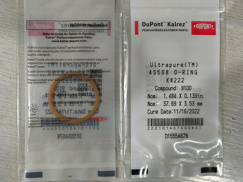
An O-ring cannot function in isolation; it is one half of a system, with the gland geometry forming the other half. ISO 3601 and AS568 standards provide detailed dimensional recommendations for both radial (piston and rod) and axial (face) seal glands, but the designer must understand the principles behind these numbers to adapt them intelligently to specific applications.
Gland Depth and Width: The depth of the groove determines the squeeze percentage, while the width must provide sufficient volume to accommodate the O-ring plus any swelling that may occur in service. A common rule of thumb is that the gland volume should be at least 110-120% of the O-ring's cross-sectional volume to allow for thermal expansion and fluid-induced swell. Overfilling the gland—where the O-ring occupies more than approximately 85-90% of the available volume—is a recipe for rapid failure, as the constrained elastomer generates enormous stress that accelerates compression set and extrusion.
Surface Finish: The sealing surfaces and gland walls must have appropriate surface finishes. A roughness average (Ra) of 0.8 to 1.6 micrometers is generally ideal for static sealing surfaces—too rough and leakage paths persist; too smooth and the surface may lack the micro-texture needed to retain lubricant in dynamic applications. Dynamic sealing surfaces for reciprocating applications should target Ra 0.2 to 0.4 micrometers, often requiring honing, grinding, or polishing operations.
Clearance Gaps and Backup Rings: In high-pressure applications, the clearance gap between the mating components becomes critically important. When system pressure exceeds a material-dependent threshold, the elastomer will begin to extrude into this gap, initially causing minor nibbling and eventually catastrophic failure. The maximum allowable clearance gap decreases as pressure increases and as the elastomer's hardness decreases. For pressures exceeding approximately 5 MPa (725 psi), anti-extrusion backup rings—typically made from filled PTFE, nylon, or PEEK—should be incorporated into the gland design on the low-pressure side. These non-elastomeric rings bridge the clearance gap, physically blocking the O-ring from extruding.
The Shore A Hardness Spectrum
O-ring hardness, measured on the Shore A durometer scale, is a direct indicator of the material's stiffness and compression resistance. The most common hardness for general-purpose O-rings is 70 Shore A, which provides a favorable balance of conformability and extrusion resistance. A 70 Shore A O-ring can handle pressures up to approximately 10 MPa without backup rings. For higher pressures, 90 Shore A compounds offer approximately 50% greater stiffness and correspondingly improved extrusion resistance, but at the cost of reduced elasticity and greater difficulty in installation. At the soft end of the spectrum, 50-60 Shore A O-rings are used for low-pressure vacuum seals or applications requiring extreme conformability to irregular surfaces, but their near-total lack of extrusion resistance limits them to very low pressure differentials.
The Five Most Common O-Ring Failure Modes
Every failed
O-ring tells a story, and learning to read the evidence is an essential skill for any reliability engineer.
Compression Set Failure: The seal, when removed, is permanently flattened on its sealing faces and no longer round in cross-section. This results from excessive temperature, excessive squeeze, or chemical attack that degrades the polymer network. The material has lost its memory and can no longer exert adequate sealing force.
Extrusion and Nibbling: The low-pressure edge of the O-ring exhibits a ragged, chewed appearance, often with small pieces of elastomer missing. This is classic high-pressure extrusion damage, indicating that the clearance gap was too large for the pressure/material combination. The solution is tighter clearances, harder O-rings, or backup rings.
Spiral Failure: The O-ring shows a distinctive twisted, spiral pattern of surface cuts. This occurs exclusively in dynamic applications when the O-ring rolls in its groove rather than sliding. Causes include insufficient squeeze, excessive friction due to poor lubrication, or eccentricity between the piston and bore.
Explosive Decompression: The O-ring is blistered internally or has a spongy, porous appearance. This occurs when high-pressure gas dissolves into the elastomer and then rapidly expands when system pressure is suddenly released. The gas cannot escape quickly enough and literally tears the material apart from the inside. Special ED-resistant compounds with high mechanical strength and formulations that resist gas absorption are required.
Plasticizer Extraction: The O-ring has shrunk significantly and become hard and brittle. This occurs when a plasticized compound is exposed to a fluid that selectively leaches out the plasticizer, causing volume loss and embrittlement. The solution is to use a compound that does not rely on extractable plasticizers for its flexibility.