What Is MTBF?
MTBF (Mean Time Between Failures) is the average time between consecutive failures of a repairable system or component, typically expressed in hours, and is the dominant reliability metric for
semiconductor front-end equipment. MTBF is calculated as total operating time divided by the number of failures over a defined period.
MTBF vs related metrics:
|
Metric |
Definition |
Use |
|
MTBF |
Mean Time Between Failures |
Repairable systems |
|
MTTF |
Mean Time To Failure |
Non-repairable components |
|
MTTR |
Mean Time To Repair |
Service time |
|
Availability |
MTBF / (MTBF + MTTR) |
Uptime percentage |
|
Lifetime |
Total useful life |
Non-repairable components |
For semiconductor tools, MTBF is typically 500–2000 hours for major subsystems, giving availability > 95 % when MTTR is < 8 hours.
What Is Component MTBF for Front-End Equipment?
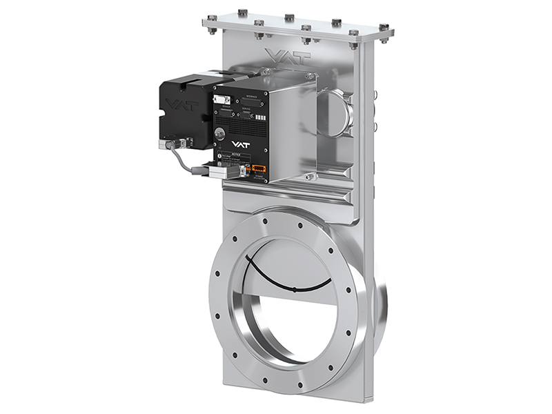
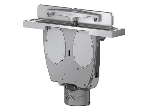
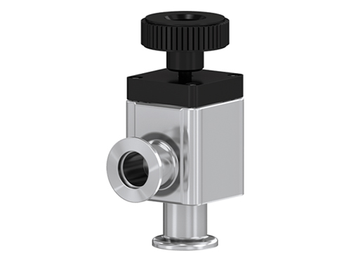
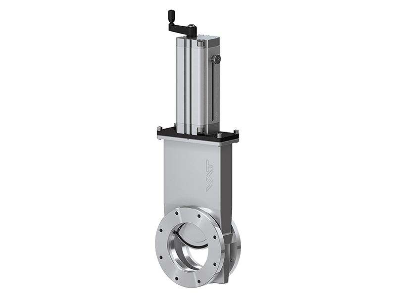
Component MTBF for front-end equipment varies widely by component type, operating conditions, and preventive maintenance intervals, with typical production MTBF values of 500–2000 hours for ESC, 1000–5000 hours for slit valve door, 1000–3000 hours for VAT vacuum valve, and 500–3000 hours for FFKM O-rings. Component MTBF is determined by wear, plasma erosion, and operator handling.
|
Component |
Production MTBF (typ.) |
Driver |
PM interval |
|
ESC |
500–2000 h |
Plasma erosion, dielectric wear |
6–18 months |
|
Slit valve door |
1000–5000 h |
Cycle wear, particle |
12–24 months |
|
VAT vacuum valve (FFKM) |
1000–3000 h |
Cycle, leak rate |
12–24 months |
|
VAT vacuum valve (FKM) |
500–1500 h |
Cycle, leak rate |
6–12 months |
|
FFKM O-ring |
500–3000 h |
Compression set, plasma |
6–18 months |
|
Wafer transfer robot |
5000–10,000 h |
Bearing wear, particle |
1–2 years |
|
Gas MFC |
2000–5000 h |
Sensor drift, valve wear |
1–2 years |
|
Throttle valve |
1000–3000 h |
Cycle wear |
1–2 years |
For high-uptime production fabs, components are replaced at 50–80 % of rated cycle life to avoid unscheduled downtime.
What Is Availability?
Availability is the percentage of time that a system is in operational state, calculated as MTBF / (MTBF + MTTR), and is the dominant operational metric for semiconductor fabs, with production tools targeting > 90 % availability and world-class fabs targeting > 95 %. Availability is increased by improving MTBF (longer time between failures) or reducing MTTR (faster repair).
Availability calculation:
Availability = MTBF / (MTBF + MTTR)
For MTBF = 1000 h, MTTR = 4 h: Availability = 1000 / 1004 = 99.6 %
For MTBF = 500 h, MTTR = 8 h: Availability = 500 / 508 = 98.4 %
For MTBF = 200 h, MTTR = 12 h: Availability = 200 / 212 = 94.3 %
For production tools, MTBF and MTTR are tracked continuously and availability targets are set per tool type and process step.
What Is Preventive Maintenance (PM)?
Preventive maintenance (PM) is the scheduled replacement of components at fixed intervals (cycle count, hours, or calendar time) to prevent unscheduled downtime, with PM intervals determined by manufacturer recommendation, fab experience, and process uptime target. PM is the most effective way to improve tool availability.
|
PM type |
Frequency |
Examples |
|
Minor PM |
Weekly |
Inspection, cleaning, calibration |
|
Major PM |
Monthly to quarterly |
Seal replacement, chamber clean |
|
Component replacement |
6–24 months |
ESC, slit valve door, VAT valve |
|
Chamber rebuild |
12–36 months |
Wall replacement, full chamber service |
For production tools, PM is scheduled during planned downtime (typically weekends, holidays) to avoid impacting production. Predictive maintenance programs use MTBF and operating-condition data to optimize PM intervals.
What Is the Failure Distribution?
Component failure follows the classic "bathtub curve" with three regions: infant mortality (high failure rate at start of life), useful life (low constant failure rate), and wear-out (increasing failure rate at end of life). Preventive maintenance targets the wear-out region.
|
Region |
Failure rate |
Action |
|
Infant mortality |
High |
Burn-in at factory |
|
Useful life |
Low |
Monitor, run to wear-out |
|
Wear-out |
Increasing |
Replace at PM |
For new component designs, burn-in (100–500 hours of operation) is used to screen out infant mortality failures. For mature components, the useful life is the dominant operating period.
What Is FMEA?
FMEA (Failure Mode and Effects Analysis) is a systematic method for identifying potential failure modes of a component or system, evaluating the severity, occurrence, and detectability of each failure, and prioritizing mitigation actions. FMEA is the standard reliability tool for semiconductor component design.
FMEA scoring:
Severity (S). 1 (no impact) to 10 (catastrophic).
Occurrence (O). 1 (very rare) to 10 (very frequent).
Detectability (D). 1 (always detected) to 10 (never detected).
RPN (Risk Priority Number). S × O × D, target < 100.
For semiconductor components, severity ratings include wafer scrap (S = 8–10), tool downtime (S = 6–8), and degraded performance (S = 3–5). High-RPN failures drive the mitigation priority.
What Is the Reliability Block Diagram?
A reliability block diagram (RBD) is a graphical representation of the components in a system and their reliability dependencies, used to calculate the system reliability and identify the critical components. RBD is used in semiconductor tool design to identify the dominant reliability contributors.
|
Component |
Series / parallel |
MTBF contribution |
|
ESC |
Series (in tool) |
Dominant (high wear) |
|
Slit valve door |
Series |
Dominant (high cycle) |
|
VAT valve |
Series |
Moderate |
|
FFKM seals |
Series |
Moderate to dominant |
|
Wafer transfer robot |
Series |
Dominant (complex) |
In a series system, the system MTBF is determined by the lowest component MTBF. For parallel redundant components, the system MTBF is significantly higher.
What Is Accelerated Life Testing?
Accelerated life testing (ALT) is the application of elevated stress (temperature, pressure, cycle rate, plasma power) to a component to accelerate failure and predict service life, with the result extrapolated to operating conditions using a physics-of-failure model. ALT is the standard method for predicting component MTBF before field deployment.
|
ALT method |
Stress |
Application |
|
Thermal aging |
Temperature |
Seals, polymers |
|
Cycle testing |
Cycle rate |
Valves, slit doors |
|
Plasma aging |
Plasma power |
ESC, seals |
|
Vibration |
Vibration |
Robots, actuators |
For FFKM O-rings, thermal aging at +250 °C (vs. operating +150 °C) accelerates compression set. For slit valve doors, cycle testing at 10× normal rate (typ. 10 Hz vs. 1 Hz) accelerates wear.
What Are the Standard Reliability Standards?
The standard reliability standards for semiconductor front-end equipment are SEMI E10 (reliability terminology), SEMI E12 (component cycle testing), SEMI E47 (equipment reliability), and IEC 61508 (functional safety). Compliance with these standards is required for OEM and Tier-1 supplier qualification.
|
Standard |
Scope |
Application |
|
SEMI E10 |
Reliability terminology |
General |
|
SEMI E12 |
Component cycle testing |
Seals, valves |
|
SEMI E47 |
Equipment reliability |
Tools |
|
IEC 61508 |
Functional safety |
Safety systems |
|
ISO 9001 |
Quality management |
General |
|
ISO 13849 |
Safety of machinery |
Safety systems |
Hitron's About Us page describes the company's quality and reliability programs aligned with these standards.
What Is the Cost of Downtime?
Semiconductor fab downtime is the most expensive operational loss, with advanced-node fabs losing $1–5 million per hour of unplanned downtime, making component reliability and preventive maintenance critical investments. The cost of downtime dominates the TCO calculation.
|
Fab type |
Downtime cost (typ.) |
|
Legacy fab (> 28 nm) |
$100,000 – $500,000 / hour |
|
Advanced fab (7–16 nm) |
$500,000 – $1,000,000 / hour |
|
Leading-edge fab (≤ 5 nm) |
$1,000,000 – $5,000,000 / hour |
For 300 mm advanced fabs, an unplanned downtime of 4 hours can cost $2–20 million, making component reliability and PM discipline critical.
What Is the TCO Calculation?
TCO (Total Cost of Ownership) is the sum of all costs associated with a component over its lifetime, including acquisition cost, installation cost, operating cost, maintenance cost, and downtime cost. TCO is the standard metric for component selection in production fabs.
TCO = Acquisition + Installation + (Operating × Life) + (Maintenance × Life) + (Downtime × Failure rate × Life)
For a $10,000 ESC with 12-month life in a $1 million / hour downtime fab:
Acquisition: $10,000
Installation: $2,000
Operating: $1,000 / year (cooling, power)
Maintenance: $5,000 / year (inspection, cleaning)
Downtime: $1,000,000 × 0.01 (1 % failure rate) = $10,000 / year
TCO for 1 year: $10,000 + $2,000 + $1,000 + $5,000 + $10,000 = $28,000 / year
For high-downtime-cost fabs, investing in higher-MTBF components is justified even at higher acquisition cost.
Frequently Asked Questions
Q: What is MTBF?
A: MTBF (Mean Time Between Failures) is the average time between consecutive failures of a repairable system or component, typically expressed in hours, and is the dominant reliability metric for semiconductor front-end equipment.
Q: What is typical MTBF for a production ESC?
A: 500–2000 hours depending on plasma chemistry, temperature, and uptime. PM interval is typically 6–18 months.
Q: What is typical MTBF for a slit valve door?
A: 1000–5000 hours depending on cycle rate and FFKM compound. PM interval is typically 12–24 months.
Q: What is the relationship between MTBF and availability?
A: Availability = MTBF / (MTBF + MTTR). For MTBF = 1000 h and MTTR = 4 h, availability = 99.6 %.
Q: What is the cost of downtime for an advanced fab?
A: $1–5 million per hour for leading-edge fabs (≤ 5 nm), $0.5–1 million per hour for advanced fabs (7–16 nm).
Q: What is FMEA?
A: FMEA (Failure Mode and Effects Analysis) is a systematic method for identifying potential failure modes, evaluating severity / occurrence / detectability, and prioritizing mitigation actions.
Q: What is accelerated life testing?
A: ALT is the application of elevated stress (temperature, cycle rate, plasma power) to accelerate failure and predict service life using a physics-of-failure model.
Q: What is the difference between PM and PdM?
A: PM (preventive maintenance) is scheduled at fixed intervals. PdM (predictive maintenance) is condition-based, using sensor data to predict failure.
Q: Does Hitron support reliability programs?
A: Yes. Hitron's About Us page describes the company's quality and reliability programs. The Product page lists the components that Hitron supplies for production fabs.
Conclusion
MTBF and availability are the dominant reliability metrics for semiconductor front-end equipment components, with production targets of 500–10,000 hours MTBF depending on the component and > 95 % availability. PM discipline, FMEA, ALT, and TCO analysis drive the reliability program. Hitron's About Us page describes the company's quality and reliability programs, with the Product page listing the front-end equipment components that Hitron supplies for production fabs and the Application page describing process integration. For product range, certifications, and engineering support, consult the Contact Us page.