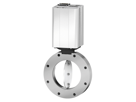
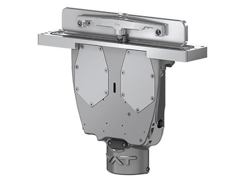
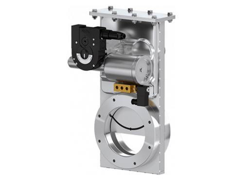
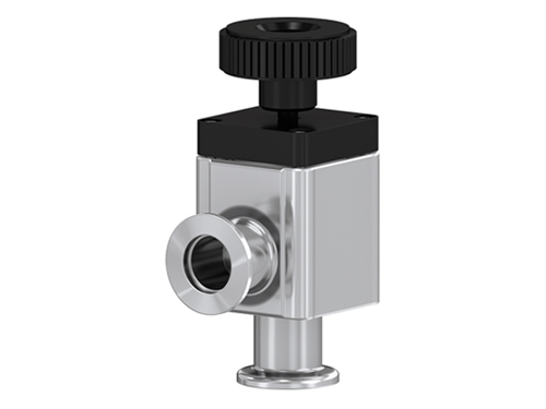
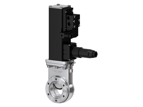
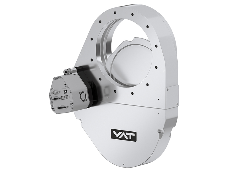
High Vacuum Butterfly Control Valve: Throttling Is A Control Problem Before It Is A Hardware Problem
Release time:2026-12-28
Visits:17
Most valves in a vacuum system are either open or closed. A high vacuum butterfly control valve is neither. It sits partway through its stroke for most of its working life, holding a chamber at a pressure setpoint while gas flows in and a pump pulls out.
That changes what "good" means. A gate valve is judged on leak rate and cycle life. A butterfly control valve has to be judged on resolution, repeatability and how it behaves inside a feedback loop — because a valve that is mechanically fine can still make a pressure loop oscillate all afternoon.
Wuxi Hitron Semiconductor Co., Ltd. supplies vacuum valve components and replacements for front-end equipment, alongside FFKM seals, slit valve doors and electrostatic chuck hardware. This note covers the control-side reasoning we use when a process engineer asks why a chamber will not hold pressure.
Why a Butterfly Disc Works as a Throttle
A disc rotating inside a bore changes flow area continuously with angle. At 90° to the flow it is nearly closed; at 0° it is nearly transparent. The relationship is not linear, which is the source of most tuning trouble.
The practical consequence: most of the useful control range lives in a narrow band of disc angle. For many butterfly geometries, roughly 20° to 70° covers the span from "barely throttling" to "almost closed." Below 20° the valve does very little; above 70° small angle changes produce large pressure changes. A controller tuned for the middle of the band will be sluggish at one end and unstable at the other.
Control Valve, Not Shutoff Valve
|
Characteristic |
Shutoff valve (gate, angle, ball) |
Butterfly control valve |
|
Normal position |
Fully open or fully closed |
Partly open, continuously modulating |
|
Design priority |
Leak rate, cycle life |
Resolution, repeatability, linearity |
|
Seat design |
Tight seat, often elastomer or metal |
Often no tight seat; a clearance seal or soft seat for throttling |
|
Actuator |
Two-position pneumatic or motor |
Modulating, with position feedback and often a controller |
|
Failure mode that matters |
Leaks |
Hunts, sticks, loses resolution |
|
Typical leak spec |
10⁻⁹ mbar·L/s class |
Not intended as an isolation device |
Do not use a
butterfly control valve as the primary isolation device on a chamber. It is a throttling element. If isolation is required, add a gate or angle valve in series and let the butterfly do the modulating.
The Loop Around the Valve
A pressure control loop in a vacuum chamber has four parts, and the valve is only one of them:
1. Sensor. A capacitance diaphragm gauge or a Pirani/CDG combination, depending on the pressure decade. Sensor resolution sets the floor for everything downstream.
2. Controller. Reads the gauge, compares to setpoint, and commands a disc angle. On many tools this is a dedicated pressure controller rather than the main tool PLC, because the loop rate is fast.
3. Actuator. Converts the command into disc position. Stepper or servo motor with gear reduction; pneumatic actuation is rare in throttling service because position control is poor.
4. Valve. The disc and body. Its conductance curve is the plant the controller has to work with.
Three of those four are electronic and can be checked with a laptop. The valve is the part that fouls, wears and drifts. When a loop starts misbehaving after a year of stable operation, look at the valve first.
Where the Disc Spends Its Time
Think in terms of three operating regions, and tune the loop around the one your recipe actually uses:
- Low angle (near open). Very small pressure response per degree. The loop tends to be stable but slow, and the valve can appear to "not respond." Nothing is broken; the plant gain is simply small here.
- Mid angle. The useful region. Plant gain is moderate, response is predictable, and most recipes are best specified to run here.
- High angle (near closed). Large pressure response per degree. This is where hunting appears: the controller overcorrects, the disc overshoots, pressure oscillates, and eventually the actuator wears at the end stop.
If a recipe sits permanently in the high-angle region, the valve is undersized for the gas flow or oversized for the pump. Fix the sizing rather than detuning the loop.
Why Valves Hunt, and What Stops It
Pressure oscillation on a throttled chamber usually traces to one of five causes:
|
Symptom |
Probable cause |
What to check |
|
Pressure oscillates with a regular period |
Loop gain too high for the operating region, or controller derivative too aggressive |
Reduce gain; verify the loop is not tuned at the wrong setpoint |
|
Pressure drifts then corrects in steps |
Actuator resolution or feedback quantisation |
Position encoder resolution; gear backlash |
|
Pressure sags when gas flow increases, recovers slowly |
Valve near its fully open limit; insufficient conductance |
Disc angle at the setpoint; valve sizing against maximum flow |
|
Pressure creeps upward over hours |
Deposition on the disc changing its effective conductance |
Inspect disc and bore for film build-up |
|
Valve sticks then jumps |
Bearing or drive wear; contamination in the bore |
Manual stroke test; torque signature |
The most common mistake is re-tuning the controller when the actual problem is a partially blocked bore or a worn bearing. A valve that used to sit at 45° and now sits at 68° for the same recipe has lost conductance, and no PID setting will restore it.
Deposition, Particles and Service Interval
In a process chamber, the throttling valve sees the exhaust stream. That means it sees everything the chamber did not consume: unreacted precursor, etch by-products, and particles.
- Film build-up on the disc and bore changes conductance and, eventually, can cause the disc to drag. On CVD-type processes this is the dominant maintenance driver.
- By-product powder in etch lines can accumulate at the bore edge and break loose as particles.
- Seal and bearing lubrication in the actuator is a separate contamination path; the wrong grease migrates into the bore under vacuum.
Practical service guidance: inspect the disc and bore at every chamber wet clean, record the disc angle at a reference recipe, and treat a drift of more than a few degrees as a signal to inspect rather than to re-tune. The angle log is the cheapest diagnostic available.
Specification Table
|
Parameter |
What to define |
Why |
|
Flange and bore size |
Nominal bore, flange standard, face-to-face length |
Fit and conductance; substitute geometry changes the loop behavior |
|
Pressure control range |
Minimum and maximum controlled pressure |
Determines gauge choice and valve size |
|
Maximum gas flow |
Flow at the highest process step |
Sets the required conductance at the operating point |
|
Leak requirement |
Whether any isolation function is expected |
A butterfly is a throttle, not a seal |
|
Disc and body material |
Stainless steel, coating option for corrosive exhaust |
Erosion and particle life |
|
Actuator |
Stepper or servo; resolution; torque margin |
Repeatability and hunting behavior |
|
Position feedback |
Analog or digital; independent limit signals |
Diagnostics and loop stability |
|
Control interface |
0–10 V, 4–20 mA, or digital fieldbus |
Integration with the pressure controller |
|
Bakeout and temperature |
Internal and ambient temperature limits |
Material and seal choice |
|
Cycle and duty |
Continuous modulation hours per day |
Bearing and drive life |
Where the tool already has an OEM reference, match it. A
butterfly control valve that differs in bore, disc profile or stroke will not reproduce the original pressure curve, and the recipe that was tuned on the old valve will need re-qualification.
Why Buy Control Valves From Hitron
Wuxi Hitron Semiconductor Co., Ltd. manufactures and supplies semiconductor front-end equipment components from Wuxi, Jiangsu — FFKM seals and Kalrez O-ring replacements, slit valve doors, electrostatic chuck hardware, wafer transfer components and vacuum valve replacements, with a 3,000 m² workshop and more than 100 client companies served.
For a high vacuum butterfly control valve, what we bring to the conversation is the process side: we will look at the recipe's pressure and flow envelope, the pump curve and the existing disc angle log before recommending a bore size or an actuator. Where an OEM reference exists — for example the 64246-JE52-BDY1 high vacuum control gate reference or the 12144-PA44-0001 transfer valve reference — we match geometry first and then confirm the control interface.
If a chamber will not hold pressure, send the pressure trace, the gas flow at each step and the disc angle if the controller logs it. In most cases the answer is visible in that data before anyone needs to remove a valve.
Contact: Jerry@hitronsemi.com · +86 18101522032 · Wuxi, Jiangsu, China